Don’t Be Casual in Your Selection of Borosilicate Fibers for Precision Lighting Systems
Basing your optical component selections on single properties like numerical aperture (N.A.) or fiber diameter can backfire on you.
However, you can reduce the probability of potential problems by reviewing real-life data revealing the impact of varied fiber-optic formulations on the transmission of broad-spectrum light. After assessing this post on fiber properties and potential pitfalls in their selection, your optical systems engineers will be equipped to make more informed decisions.
Test Methodology
A number of fiber-optic cables were prepared: all had common length, common bundle diameter, common sheathing, and common ferrules.
Our testing looked at transmission (flux), beam angle, and selective absorption; the method of polishing fiber, index of refraction of the fiber, and the fiber diameters was varied. All fiber bundles were powered using a 250-watt 4-channel LED fiber-optic illuminator manufactured by Techniquip.
Flux was collected using a Labsphere integrating sphere. All other data was collected by a spectrometer positioned 250 mm from the fiber exit face.
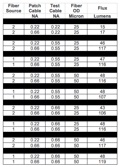
Two series of Fiber Optic Transmission Testing Completed 2.23.16 tests were conducted. In the first the cables were powered directly from the LED illuminator. In the second series of tests the output of the LED illuminator was sent through a preconditioning patch cable to reduce NA. This was done so that better estimates of the pure transmission losses could be determined.
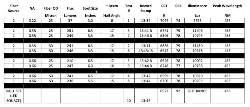
Series 1 Test Data
Series 2 Test Data
Spectral Composition of Light From Source and After Exiting Bundles of Varying N.A.

Results with Definitive Implications
The data showed a huge difference in flux between 0.22 N.A. fiber and the more common 0.55 / 0.66 N.A. fibers.
For a system requiring low angles, there are likely more effective ways to transmit light and block stray light than using 0.22 N.A. fibers. Contact TechniQuip for more information on better techniques and equipment for achieving the best results.
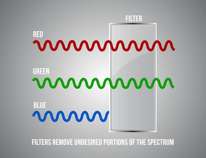
The data shows a dramatic shift in Corrected Color Temperature (CCT) and drop in Color Rendering Index (CRI) between the source and the light exiting all the various fibers. You can see here that, for a desired CCT / CRI outcome, looking at the source properties is not sufficient to ensure a good design.
The data also showed that relative to other factors, the impact of polishing method and fiber diameters was negligible.
The above testing helped us complete the development of a high-power OEM darkfield lighting system for semiconductor inspection applications using a quad‐LED illuminator and borosilicate fiber optics.
TechniQuip is a leading supplier of precision lighting systems to increase the productivity of people and machines working in surgery, semiconductor inspection, quality control, and a variety of other fields.
For questions about our tests and the results, or for assistance with your lighting project please contact us at (925) 251‐9030 or via email at orders@techniquip.com
The post Don’t Be Casual in Your Selection of Borosilicate Fibers for Precision Lighting Systems appeared first on TechniQuip.


